Color model
The LBPM color model is implemented by combining a multi-relaxation time D3Q19 lattice Boltzmann equation (LBE) to solve for the momentum transport with two D3Q7 LBEs for the mass transport. The color model will obey strict mass and momentum conservation while minimizing diffusive fluxes across the interface between fluids. The color model is a good choice for modeling dense fluids that are strongly immiscible (e.g. water-oil systems). Due to the strong anti-diffusion in the interface region, the color model is not suitable for modeling processes such as Ostwald ripening that depend on diffusive fluxes between fluid phases.
A typical command to launch the LBPM color simulator is as follows
`
mpirun -np $NUMPROCS lbpm_color_simulator input.db
`
where $NUMPROCS is the number of MPI processors to be used and input.db is
the name of the input database that provides the simulation parameters.
Note that the specific syntax to launch MPI tasks may vary depending on your system.
For additional details please refer to your local system documentation.
Simulation protocols
Simulation protocols are designed to make it simpler to design and execute common computational experiments. Protocols will automatically determine boundary conditions needed to perform a particular simulation. LBPM will internall set default simulation paramaters that can be over-ridden to develop customized simulations.
Analysis capabilities
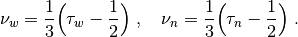
Model parameters
The essential model parameters for the color model are
alpha– control the interfacial tension between fluids –
beta– control the width of the interface –
tauA– control the viscosity of fluid A –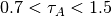
tauB– control the viscosity of fluid B –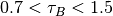
rhoA– control the viscosity of fluid A –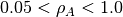
rhoB– control the viscosity of fluid B –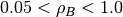
Model Formulation
Two LBEs are constructed to model the mass transport, incorporating the anti-diffusion
![$$
A_q(\bm{x} + \bm{\xi}_q \delta t, t+\delta t) = w_q N_a \Big[1 + \frac{\bm{u} \cdot \bm{\xi}_q}{c_s^2}
+ \beta \frac{N_b}{N_a+N_b} \bm{n} \cdot \bm{\xi}_q\Big] \;
$$](../../../_images/math/6983c920fe16fe539862296a760684063b09aca7.png)
![$$
B_q(\bm{x} + \bm{\xi}_q \delta t, t+\delta t) =
w_q N_b \Big[1 + \frac{\bm{u} \cdot \bm{\xi}_q}{c_s^2}
- \beta \frac{N_a}{N_a+N_b} \bm{n} \cdot \bm{\xi}_q\Big]\;,
$$](../../../_images/math/ca4c3b8464267976b0015807f60c3d8e8459b250.png)
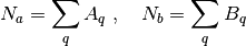
The number density for each fluid is obtained from the sum of the mass transport distributions
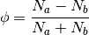
The phase indicator field is then defined as
The fluid density and kinematic viscosity are determined based on linear interpolation
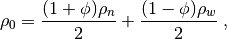
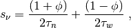
where
These values are then used to model the momentum transport. The LBE governing momentum transport is defined based on a MRT relaxation process with additional terms to account for the interfacial stresses
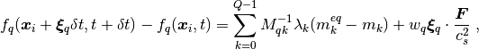
Where  is an external body force and
  is the speed of sound for the LB model.
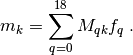
The moments are linearly indepdendent:
is the speed of sound for the LB model.
The moments are linearly indepdendent:
The relaxation parameters are determined from the relaxation time:

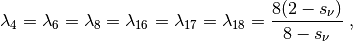
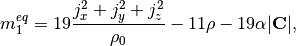
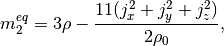
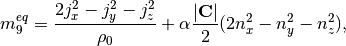
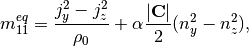
The non-zero equilibrium moments are defined as


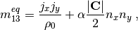
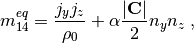
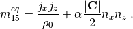
where the color gradient is determined from the phase indicator field

and the unit normal vector is

Boundary Conditions
The following external boundary conditions are supported by lbpm_color_simulator
and can be set by setting the BC key values in the Domain section of the
input file database
BC = 0– fully periodic boundary conditionsBC = 3– constant pressure boundary conditionBC = 4– constant volumetric flux boundary condition
For BC = 0 any mass that exits on one side of the domain will re-enter at the other
side. If the pore-structure for the image is tight, the mismatch between the inlet and
outlet can artificially reduce the permeability of the sample due to the blockage of
flow pathways at the boundary. LBPM includes an internal utility that will reduce the impact
of the boundary mismatch by eroding the solid labels within the inlet and outlet layers
(https://doi.org/10.1007/s10596-020-10028-9) to create a mixing layer.
The number mixing layers to use can be set using the key values in the Domain section
of the input database
InletLayers = 5– set the number of mixing layers to5voxels at the inletOUtletLayers = 5– set the number of mixing layers to5voxels at the outlet
For the other boundary conditions a thin reservoir of fluid (default 3 voxels)
is established at either side of the domain. The inlet is defined as the boundary face
where z = 0 and the outlet is the boundary face where z = nprocz*nz. By default a
reservoir of fluid A is established at the inlet and a reservoir of fluid B is established at
the outlet, each with a default thickness of three voxels. To over-ride the default label at
the inlet or outlet, the Domain section of the database may specify the following key values
InletLayerPhase = 2– establish a reservoir of component B at the inletOutletLayerPhase = 1– establish a reservoir of component A at the outlet
Example data
Example data can be downloaded from https://www.digitalrocksportal.org/projects/326