Color model – Fractional Flow Protocol
The fractional flow protocol is designed to perform steady-state relative permeability simulations by using an internal routine to change the fluid saturation by adding and subtracting mass to the fluid phases. The mass density is updated for each fluid based on the locations where the local rate of flow is high.
Enabling the fractional flow protocol will automatically set the following default settings:
fractional_flow_increment = 0.05- target change in saturation between steady pointsendpoint_threshold = 0.1- termination criterion based on the relative flow rates of fluidsmass_fraction_factor = 0.006- percentage change to the mass fraction (per iteration)fractional_flow_epsilon = 5.0e-6- control the threshold velocity
skip_timesteps = 50000- timesteps to spend in adaptive part of algorithmmin_steady_timesteps = 1000000- minimum number of timesteps per steady pointmax_steady_timesteps = 1000000- maximum number of timesteps per steady point
Any of these values can be manually overriden by setting the appropriate key to a custom value
within the FlowAdaptor section of the input file database. The fractional flow
will enforce periodic boundary conditions BC = 0, and is not compatible with other
boundary condition routines. A warning message will be printed if BC is set to a value
other than 0.
The basic idea for the fractional flow algorithm is to define an algorithm to modify the fluid saturation that will:
minimize the introduction of end effects and gradients in saturation
respect the structure and connectivity of the fluid phases to the maximum extent
minimize the transient disruption to the flow behavior so that fewer timesteps are required to reach steady state
The strategy used to accomplish these objectives is to change saturation by either increasing
or decreasing the mass within each fluid, depending on the sign of mass_fraction_factor.
If mass_fraction_factor is positive, the algorithm will remove mass from fluid A and add
mass to fluid B. The opposite will happen if mass_fraction_factor is negative. The algorithm
will selectively add mass to voxels where the local flow rate is high, since these will generally
correspond to the mobile (i.e. not disconnected) fluid regions. A local weighting function is determined
from the velocity 
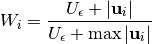
where  is the maximum flow speed within fluid
  and
is a threshold speed that is set to minimize the influence of spurious
currents on the mass seeding algorithm. The sum of the weighting function is used to normalize
the local weights so that the added mass will match the value specified by
and
is a threshold speed that is set to minimize the influence of spurious
currents on the mass seeding algorithm. The sum of the weighting function is used to normalize
the local weights so that the added mass will match the value specified by mass_fraction_factor.
If the flow is slower than , the algorithm will tend to add mass evenly to the system.
For example, if the water is only present in films that flow very slowly, then mass will
be evenly seeded throughout entire water film. Alternatively, if one or both fluids
flows through distinct channels, the mass will be disproportionately added to these
channels where the rate of flow is high. As system relaxes, the mass will redistribute
spatially, causing a change to the fluid saturation.
Color {
   protocol = "fractional flow"
   capillary_number = 1e-4            // capillary number for the displacement
   timestepMax = 1000000              // maximum timtestep
   alpha = 0.005                      // controls interfacial tension
   rhoA = 1.0                         // controls the density of fluid A
   rhoB = 1.0                         // controls the density of fluid B
   tauA = 0.7                         // controls the viscosity of fluid A
   tauB = 0.7                         // controls the viscosity of fluid B
   F = 0, 0, 1.0e-5                   // body force
   WettingConvention = "SCAL"         // convention for sign of wetting affinity
   ComponentLabels = 0, -1, -2        // image labels for solid voxels
   ComponentAffinity = 1.0, 1.0, 0.6  // controls the wetting affinity for each label
   Restart = false
}
Domain {
   Filename = "Bentheimer_LB_RelPerm_intermediate_oil_wet_Sw_0p37.raw"
   ReadType = "8bit"              // data type
   N = 900, 900, 1600             // size of original image
   nproc = 2, 2, 2                // process grid
   n = 200, 200, 200              // sub-domain size
   offset = 300, 300, 300         // offset to read sub-domain
   InletLayers = 0, 0, 6          // number of mixing layers at the inlet
   OutletLayers = 0, 0, 6         // number of mixing layers at the outlet
   voxel_length = 1.66            // voxel length (in microns)
   ReadValues = -2, -1, 0, 1, 2   // labels within the original image
   WriteValues = -2, -1, 0, 1, 2  // associated labels to be used by LBPM
   BC = 0                         // boundary condition type (0 for periodic)
}
Analysis {
   analysis_interval = 1000           // logging interval for timelog.csv
   subphase_analysis_interval = 5000  // loggging interval for subphase.csv
   visualization_interval = 100000    // interval to write visualization files
   N_threads = 4                      // number of analysis threads (GPU version only)
   restart_interval = 1000000         // interval to write restart file
   restart_file = "Restart"           // base name of restart file
}
Visualization {
   write_silo = true     // write SILO databases with assigned variables
   save_8bit_raw = true  // write labeled 8-bit binary files with phase assignments
   save_phase_field = true  // save phase field within SILO database
   save_pressure = false    // save pressure field within SILO database
   save_velocity = false    // save velocity field within SILO database
}
FlowAdaptor {
   min_steady_timesteps = 100000     // minimum number of timesteps per steady point
   max_steady_timesteps = 250000     // maximum number of timesteps per steady point
   mass_fraction_factor = 0.006      // controls the rate of mass seeding in adaptive step
   fractional_flow_increment = 0.05  // saturation change after each steady point
   endpoint_threshold = 0.1          // endpoint exit criterion (based on flow rates)
}