Color model – Subphase Analysis
The subphase analysis routine for the LBPM color model logs a time series
of averaged information to the space-delimited CSV file subphase.csv.
The subphase_analysis_interval key should be specified to control the interval at
to perform basic analysis, which corresponds to the number of simulation timesteps
to perform between analyses. The subphase analys routine performs the following functions
analyzes the connectivity of fluid phases using a connected components algorithm
constructs iso-surfaces to represent interfaces within the system
computes averages of physical quantities based on the defined entities
Since it is more computationally expensive to carry out these operations compared to the
basic analysis, it may be useful to choose subphase_analysis_interval to be larger than
analysis_interval. Nevertheless, since analysis is performed in memory, it is orders of
magnitude faster than to analyze data in situ rather than writing fields to disc. Monitoring
the performance in MLUPS provides an easy way to tune the analysis interval so that the
overall simulation performance is not subject to significant penalties.
There are three main entities that are constructed for subphase analysis
 : region of space filled by fluid w
 : region of space filled by fluid n
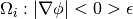 : region of space for the interface region
The phase regions are defined identical to what is reported in timelog.csv.
The interface region is defined explicitly as the portion of space where
significant composition gradients are present. For each entity, sub-entities are
constructed by running a connected components algorithm on the set. This is done to
separate the connected part of the phase from the disconnected part. This subset operation
is performed by identifying the largest connected component (based on volume)
and denoting this as the connected part of that region. The remaining portion of the
phase is lumped into a disconnected sub-entity. Subphase analysis is therefore performed
for the following six entities
wc– connected part of phase wwd– disconnected part of phase wnc– connected part of phase nnd– disconnected part of phase nic– connected part of interface regionid– disconnected part of interface region
For each entity  with
with  an isosurface is constructed to approximate the boundary of the region,
 . Once each region is identified, the following measures are determined
Geometric invariants
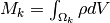
Volume –

Surface area –

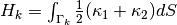
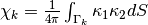
Integral mean curvature –
Euler characteristic –
Conserved quantities
Total mass within the region
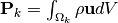
Total momentum within the region
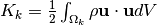
Total kinetic energy within the region
Thermodynamic quantities
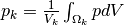
Pressure –
Solid wetting energy –

Viscous dissipation –
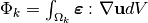
The total solid wetting energy is determined by integrating the interfacial stresses in the
immediate vicinity of the solid surface  . The integral of the
dissipation function is determined based on the viscous stress tensor, denoted by
. The integral of the
dissipation function is determined based on the viscous stress tensor, denoted by  .
.
The full list of measures are associated with the labels in subphase.csv
time– timesteprn– density for phase n (input parameter)rw– density for phase w (input parameter)nun– kinematic viscosity for phase n (input parameter)nuw– kinematic viscosity for phase w (input parameter)Fx– external force in x direction (input parameter)Fy– external force in y direction (input parameter)Fz– external force in z direction (input parameter)iftwn– interfacial tension (input parameter)wet– total solid wetting energypwc– average pressure for connected part of phase wpwd– average pressure for disconnected part of phase wpnc– average pressure for connected part of phase npnd– average pressure for disconnected part of phase nMwc– mass for connected part of phase wMwd–mass for disconnected part of phase wMwi– mass for phase within diffuse interface regionMnc– mass for connected part of phase nMnd– mass for disconnected part of phase nMni– mass for phase n within diffuse interface regionMsw– mass for component w within 2 voxels of solidMsn– mass for component n within 2 voxels of solidPwc_x– x- momentum for connected part of phase wPwd_x– x- momentum for disconnected part of phase wPwi_x– x- momentum for phase w within diffuse interfacePnc_x– x- momentum for connected part of phase nPnd_x– x- momentum for disconnected part of phase nPni_x– x- momentum for phase n within diffuse interfacePsw_x– x- momentum for phase w within 2 voxels of solidPsn_x– x- momentum for phase n within 2 voxels of solidPwc_y– y- momentum for connected part of phase wPwd_y– y- momentum for disconnected part of phase wPwi_y– y- momentum for phase w within diffuse interfacePnc_y– y- momentum for connected part of phase nPnd_y– y- momentum for connected part of phase nPni_y– y- momentum for phase n within diffuse interfacePsw_y– y- momentum for phase w within 2 voxels of solidPsn_y– y- momentum for phase n within 2 voxels of solidPwc_z– z- momentum for connected part of phase wPwd_z– z- momentum for disconnected part of phase wPwi_z– z- momentum for phase w within diffuse interfacePnc_z– z- momentum for connected part of phase nPnd_z– z- momentum for disconnected part of phase nPni_z– z- momentum for phase n within diffuse interfacePsw_z– z- momentum for phase w within 2 voxels of solidPsn_z– z- momentum for phase n within 2 voxels of solidKwc– Kinetic energy for transport within connected part of phase wKwd– Kinetic energy for transport within disconnected part of phase wKwi– Kinetic energy for transport of phase w within diffuse interface regionKnc– Kinetic energy for transport in connected part of phase nKnd– Kinetic energy for transport within disconnected part of phase nKni– Kinetic energy for transport of phase n within diffuse interface regionDwc– Viscous dissipation for conneced pathway for phase wDwd– Viscous dissipation for disconnected part of phase wDnc– Viscous dissipation for connected pathway for phase nDnd– Viscous dissipation for disconnected part of phase nVwc– Volume for connected pathway for phase wAwc– Surface area for connected pathway for phase wHwc– Integral mean curvature for connected pathway for phase wXwc– Euler characteristic for connected pathway for phase wVwd– Volume for disconnected phase wAwd– Surface area for disconnected phase wHwd– Integral mean curvature for disconnected phase wXwd– Euler characteristic for disconnected phase wNwd– Number of connected components in disconnected phase wVnc– Volume for connected pathway for phase nAnc– Surface area for connected pathway for phase nHnc– Integral mean curvature for connected pathway for phase nXnc– Euler characteristic for connected pathway for phase nVnd– Volume for disconnected phase nAnd– Surface area for disconnected phase nHnd– Integral mean curvature for disconnected phase nXnd– Euler characteristic for disconnected phase nNnd– number of connected components within disconnected phase nVi– volume for diffuse interface regionAi– surface area for boundary of diffuse interface regionHi– integral mean curvature for boundary of diffuse interface regionXi– Euler characteristic for diffuse interface regionVic– volume for connected interface regionAic– surface area for boundary of connected interface regionHic– Integral mean curvature for connected interface regionXic– Euler characteristic for connected interface regionNic– number of connected components in connected interface region